Working Principle Of Full Bridge Inverter
Inverter bridge phase single load rlc overdamped Inverter mosfet 12v outputs connections Inverter electricalbaba
The schematic diagram of a single-phase full bridge inverter | Download
Single phase full bridge inverter H-bridge inverter circuit using 4 n-channel mosfets Schematic of a full-bridge inverter
Accurate simplified inverter output
Single phase full bridge inverterInverter summary Bridge half inverter single phase using matlab power module admin july rantleInverter circuit bridge phase ic using 5kva single diagram core mosfet transformerless ac ferrite simplest driver gate pwm circuits 2kva.
Inverter circuit bridge half circuits basic transformer diagram using homemade center does tap mini two type tutorial make similarHow to design an inverter A). circuit diagram of simple full-bridge inverter with 0 o and 180 oTransformerless h-bridge inverter circuit.

Easy 150 w full-bridge inverter circuit [tested]
Simplified circuit of the full-bridge output inverter.Full bridge inverter: circuit, waveforms, working and applications Inverter bridge phase single working half voltage revolution electrical load outputInverter bridge circuit homemade using circuits wave sine modified mosfets channel kva.
Inverter phase rl circuitSummary of a full bridge inverter Single phase full bridge inverter explainedSingle phase full bridge inverter (square wave output).

Single phase full bridge inverter explained
Inverter output resistive inductiveThe schematic diagram of a single-phase full bridge inverter Full bridge inverterElectric circuit of the full bridge inverter system..
Inverter waveforms controlledInverter phase waveforms waveform output signal Single phase full bridge inverter हिन्दीSg3525 inverter circuit bridge diagram using bootstrap mosfet driver homemade channel circuits ic capacitor mosfets pdf schematic try post investigate.

Inverter circuit diagram 120 mode operation phase three bridge power formula figure electrical shown below
Single phase half bridge and full bridge inverter using matlabInverter phase principle 120° mode inverter – circuit diagram, operation and formulaElectric circuit of the full bridge inverter system..
Inverter schematic .


H-Bridge Inverter Circuit Using 4 N-channel Mosfets - Homemade Circuit

Electric circuit of the full bridge inverter system. | Download
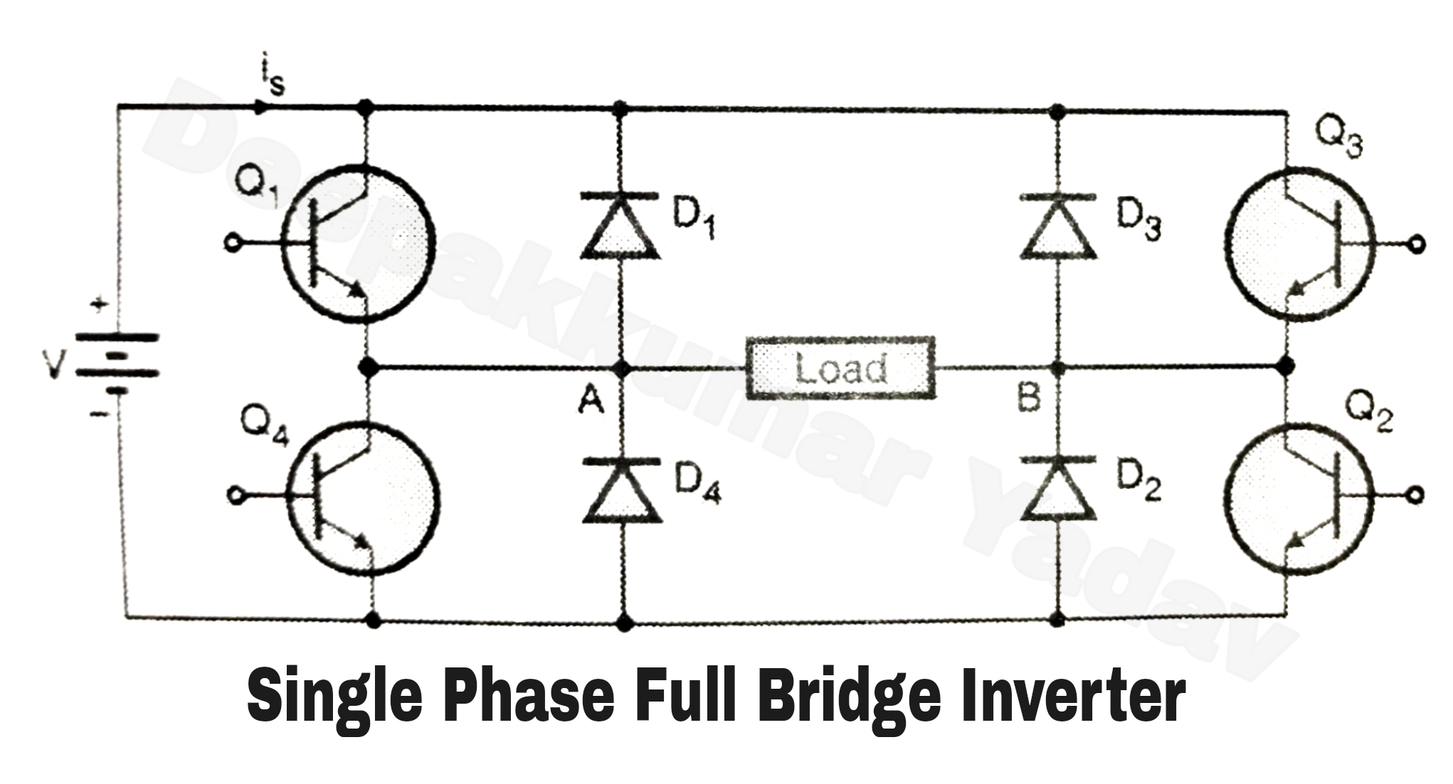
Single Phase Full Bridge Inverter (Square Wave Output)

The schematic diagram of a single-phase full bridge inverter | Download

Schematic of a full-bridge inverter | Download Scientific Diagram

Full Bridge Inverter: Circuit, Waveforms, Working And Applications

a). Circuit diagram of simple full-bridge Inverter with 0 o and 180 o

Simplified circuit of the Full-Bridge output Inverter. | Download