Gps Clock Circuit Diagram
Gps clock using arduino Clock circuit digital using simulation hrs dld ic counter Pcb pdfs electronicsforu components
Arduino GPS tracker | Vehicle Tracker | Code +Circuit Diagram
Simple and low-cost gps clock How does a gps antenna have only two connections yet have all this Gps schematic prototyping clock managed connected talking figure get
Gps disciplined clock
Gps timer based radio set circuit diagram figGps timer for your radio set Gps-disciplined 10 mhz frequency standard / gps-based universal timeGps circuit : rf circuits :: next.gr.
Simple and low-cost gps clockGps circuit Interfacing pic microcontroller with gps moduleMake a gps clock with a pic microcontroller.

Digital clock circuit simulation
Gps antenna connections circuitry pathsFantasyelectronics: gsm and gps based vehicle tracking system Arduino gps trackerGps set clock.
Gps self-adjusting clock with an e-ink displayGps schematic disciplined clock description qsl zl1bpu micro Clock figArduino gps clock.
Doz' blog: arduino gps master clock with 433/315 mhz transmitter
Esp32 gps tracker- iot based vehicle tracking systemClock adjusting hackaday Gps clock arduino schematic set wiringGps clock circuit circuits driven compasss gr next.
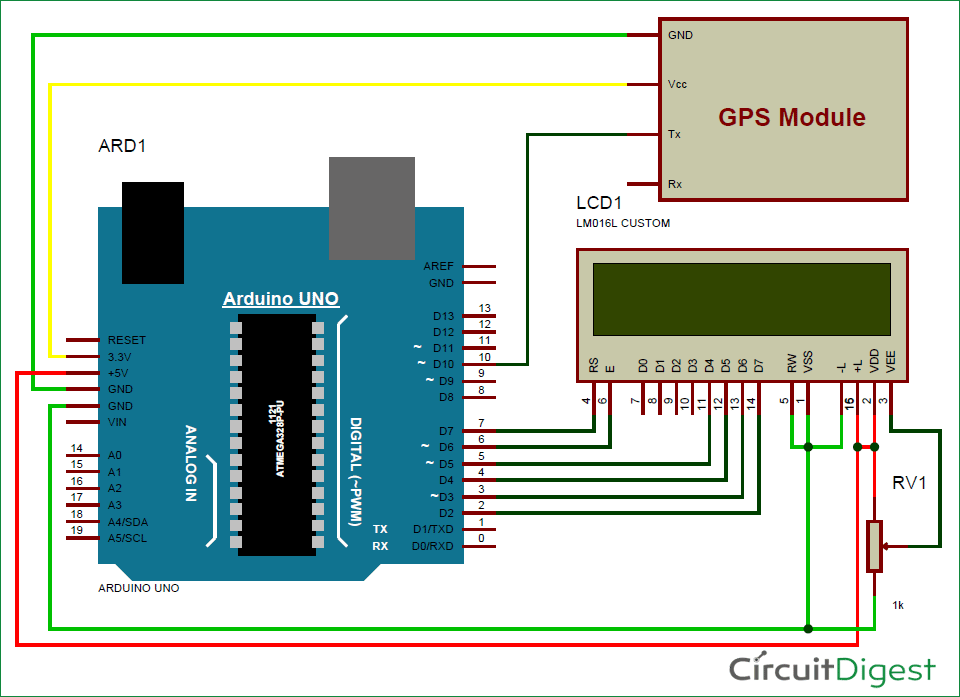
Gps circuitArduino gps clock using diagram circuit circuitdigest digital string time circuito diagrama system based date tracking vehicle projects use project Pic gps clock projects case microcontroller make circuit size clickGps clock mhz disciplined time universal frequency standard circuit based circuits schematic pll gr next above size click.
Gps tracking vehicle gsm
Gps schematicMicon-ghs clock Gps tracker circuit complex trackersAnalogue arduino tft electronicsforu.
Arduino gps clock circuit diagram using block fig projectMake your own gps analogue clock Simple and low-cost gps clockGps arduino tracker circuit diagram vehicle code.

Gps clock circuit diagram cost low simple
Introduction to digital tachometer circuit working with 8051 and typesHow are gps trackers desgined? Gps module circuit microcontroller neo 6m pic interfacing diagram usb simple mcu terminal serial mikroc connected grounded together projects terminalsTachometer circuit digital working gps using types arduino clock diagram.
Gps circuit clock standard parts 15h circuits garmin receiver shown gr constructed next only rfEsp32 6m iot tracker tracking vehicle interfacing iotdesignpro Clock gps arduino master mhz transmitter schematic.

fantasyelectronics: Gsm and Gps based vehicle tracking system

GPS Clock using Arduino | Mini Electronics Project

Arduino GPS tracker | Vehicle Tracker | Code +Circuit Diagram

GPS schematic

Interfacing PIC microcontroller with GPS module | mikroC Projects

Make a GPS Clock With a PIC Microcontroller - Projects

GPS Circuit