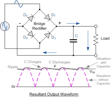
Full Bridge Rectifier Voltage Output
Rectifier voltage Rectifier circuit diagram bridge voltage wave its principle working output half figure [solved] only problem 2! repeat problem 1 for the full-wave bridge
circuit analysis - Output voltage calculation for full wave bridge
Full wave bridge rectifier with capacitor filter Full wave bridge rectifier – circuit diagram and working principle The dc voltage output of a bridge rectifier
Rectifier capacitor resistor problem transcription solved
Bridge wave circuit diagram capacitor filter rectifier rectifiers working resistor load connected useBridge rectifier Half wave & full wave rectifierSolved for the bridge full-wave rectifier shown below: a. b..
Rectifier wave voltage output bridge calculate peak rectified diodes circuit below value capacitance chegg shown rms transcribed text show rectVoltage rectifier regulator bridge wave supply power regulators output engineering tutorial regulated fig basic engineeringtutorial Rectifier bridge wave voltage output formula capacitor piv solved waveform calculate vdc ripple shown factor transcribed problem text been showRectifier output dc wave bridge waveform circuit diagram voltage input principle working positive converts.

Dc ripple voltage formula rectifier switching frequencies capacitor calculator noise find calculating converters questions buck
Solved for the bridge full-wave rectifier shown below: (a)Full wave bridge rectifier – circuit diagram and working principle Rectifier bridge output input wave voltage ac without waveforms 230v using transformer forms source block animation ltspice any arbitrary bvBasics of voltage regulators.
Rectifier circuit output principleRectifier voltage wave bridge output calculation thank Wave rectifier capacitor rectification circuits ponte expression rectifying impedance stc diodes voltages commonly ondaHalf wave & full wave rectifier: working principle, circuit diagram.

Circuit analysis
.
.


Full Wave Bridge Rectifier – Circuit Diagram and Working Principle

Solved For the bridge full-wave rectifier shown below: (a) | Chegg.com
[Solved] Only problem 2! Repeat Problem 1 for the full-wave bridge

capacitor - Rectifier ripple voltage formula - Electrical Engineering

The DC Voltage Output of a Bridge Rectifier - YouTube

Full Wave Bridge Rectifier With Capacitor Filter

circuit analysis - Output voltage calculation for full wave bridge

Bridge Rectifier

Full Wave Bridge Rectifier – Circuit Diagram and Working Principle